MIPI-DSI on i.MXRT 1060/1070

Hello everyone, this is going to be a 2 part series in which I am going to explain you about MIPI-DSI, how it works and how to use it on NXP i.MXRT1160/1170 crossover MCUs.
What is MIPI-DSI?
MIPI DSI (Mobile Industry Processor Interface Display Serial Interface) is a high-speed interface standard for connecting a display to a mobile device or embedded system. Developed by the MIPI Alliance (Formed by ARM, Nokia, ST and TI in 2003, Intel, Motorola, Samsung and Philips joined within a year), a global organization dedicated to developing interface specifications for mobile and mobile-influenced industries. MIPI DSI is designed to support the display needs of smartphones, tablets, laptops, and other portable devices. DSI only specifies a set of commands, data serialisation and packetization schemes. This packet-based approach allows for a more efficient use of bandwidth and power, making it ideal for mobile applications. The use of MIPI DSI is not limited to mobile devices, it has also been adopted in embedded systems, such as Internet of Things (IoT) devices, automotive displays and industrial displays. It does not define any actual electrical specifications, physical layer or a connector standard (like HDMI and USB). The actual electrical specifications are defined by a PHY (short for physical layer). NXP i.MXRT 1160 uses D-PHY , here D stands for Roman numerical 500 and it denotes the maximum speed of 500 mbits/sec per lane. There are other types of PHYs as well such as C-PHY, A-PHY, etc.
Now that we have some idea about what is DSI, let’s discuss about what it’s not.
- It's not a plug and Play system like HDMI or USB. It requires a specific configuration and initialization sequence to operate.
- It's meant for short distance communication only as it was designed for portable and hand-held devices. Max length is only 25-30 Cm.
- It's is not designed to interface multiples devices at same time (Unlike SPI, I2C).
How Modern Displays work?
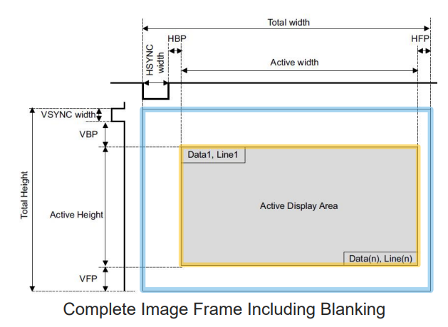
Before diving into how MIPI-DSI works we need to understand some basic terminology. All modern-day display signaling is inspired from the old day CRTs (:tv: yes those old beefy televisons). Most modern day displays uses the same raster scan technique to produce images on the screen. You can learn more about this here. This displayed image is often referred to as a Frame. Pixels are located relative to their time from the vertical and horizontal sync signals. The display process repeats itself for the next frame, and the next frame, etc… The film/video world define this timing interval at which a new frame is displayed is as Frames per Second (FPS).
Basic concepts
Horizontal Blanking Interval – When the electron beam is steered from left to right to start a new horizontal line is called horizontal retrace and the time it takes to do this process is called horizontal blanking interval.
It consists of 3 parts.
Horizontal Blanking Interval = Horizontal Front Poarch + Horizontal Sync Width + Horizontal Back Poarch
Horizontal Front Poarch = Time it takes to switch of the electron beam and turn it around.
Horizontal Sync Width = Time it takes to Steer the electron beam from Left to right side.
Horizontal Back Poarch = Time it takes to stabilize the electron beam before starting up the new line.
Similarly, we have vertical blanking interval and we have,
Vertical Blanking Interval – When the electron beam is steered from bottom left to top right, i.e from the end line of the frame to first line of the next frame to start a new frame is called vertical retrace and the time it takes in this process is called vertical blanking interval.
It also consists of 3 parts.
Vertical Blanking Interval = Vertical Front Poarch + Vertical Sync Width + Vertical Back Poarch
Pixel Clock is defined as
Pixel Clock = (Frame Height + Vertical Front Poarch + Vertical Sync Width + Vertical Back Poarch) x ( Frame Width Vertical Front Poarch + Vertical Sync Width + Vertical Back Poarch) x FPS.
so control a digital display we need at least 24 signal lanes(8 signal lane per channel for RGB),1 Hsync, 1 Vsync, 1 Pclk and 1 Data Enable, therefore a bare minimum of 28 signal lanes or pins for transmission of data. DSI takes all these parallel signals and converts them into a serialised packet data which can be sent at high speeds using only 6 lanes(2 for clk and 4 for 2 differential data pairs).It saves space on PCB and improves EMI/EMC characteristics of the product.
DSI Lanes
DSI takes RGB Parallel bus and serialize all the pixel data, commands and events into data packets. It uses DDR to transmit data, which means data is transmitted at both rising clock edge as well as falling clock edge
DSI used Differential pairs lanes to communicate between host and LCD.
We have CLOCK – Unidirectional Differential pair clock signal
DATA LANE 0 - Bidirectional Differential pair data lane.
DATA LANE n -Unidirectional Differential pair data lane (From host to LCD only)
There can be only 4 Data lanes at max.
Power Modes
- Low power Mode (LP) – All the Lanes become signal ended and non-terminated and this mode is only used to transmit commands. It uses traditional single ended CMOS IO buffers and works at 0 to 1.2V logic level.
- High Speed Mode (HS) – It used low voltage differential signaling with 50 Ohm tracks and 100 Ohms termination and this mode is only used to transmit commands. It is used to transmit high speed pixel data.
There is also a ultra-low power mode or ULPM.
Important points
- Clock Lane goes from LP mode to HS mode before any data lane.
- All data lanes go from Low Speed mode to high speed together.
- After the transmission in HS Mode all lanes go back to low power mode.
- Clk has the option to stay in HS mode for the entire duration and it is called continuous clock mode. It generally depends on the LCD controller used.
- When shifting from HS mode to LP mode, Data lanes shifts before Clk lanes.
{{< raw >}}
[HS \space bit \space clk = \frac{(Pixel \space clk * bits \space per \space pixel)}{No. \space of \space DSI \space LANES} * \frac{9}{8}]
{{< /raw>}}
Here constant 9/8 = 1.125 = DSI overhead and we keep the clock frequency slightly up to accommodate for this.
Modes of operation
-
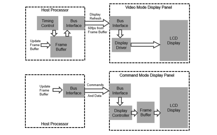
Command Mode
Command Mode refers to operation in which transactions primarily take the form of sending commands and data to a display module, that incorporates a display controller.The display controller may include local registers and a frame buffer. Systems using Command Mode write to, and read from, the registers and frame buffer memory. -
Video Mode Operation
Video Mode refers to operation in which transfers from the host processor to the peripheral take the form of a real-time pixel stream. In normal operation, the display module relies on the host processor to provide image data at sufficient bandwidth to avoid flicker or other visible artifacts in the displayed image. Video information should only be transmitted using High Speed Mode.
DSI Packets
DSI has 2 types of packets Short Type and Long type.
- Short Packets – They are 4 bytes long and can be transmitted in either LP mode or HS mode. They are generally used to transfer commands.
When transmitting Display Commands Set (DCS) the Data0 becomes the DSI Register Address and rest of the Data packets becomes the Payload or argument. DATA0 is always the display command in both Short Packet and Long Packet.
{{< image src="image2.png" alt="DSI Short Packet Structure">}}
- Long Packets – They can be 4 to 65541 bytes long and can only be transmitted in HS mode. They are generally used to transmit Pixel data but also for commands which are more than 4 bytes long.
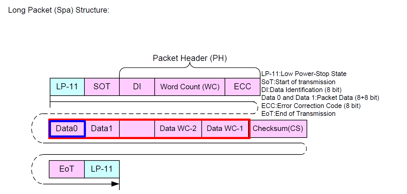
Here LP-11 on both the ends refers to low Power stop state where all the data and clock pins are at low power high level (1.2V).
To Read more about the Power state changes please refer to this.
When transmitting Display Commands Set (DCS) the Data0 becomes the DSI Register Address and rest of the Data packets becomes the Payload or argument. For commands with no payload or parameter , data1 is always 0x00H. (For ex - SWRESET (01h), ALLPOFF (22h), SLPIN (10h), ALLPON (23h), SLPOUT (11h)).
For example if sending ALLPOFF command, the packet data will look like.
Data0-22H
Data1-0xHH
In the next part I am going to show you how to do LCD bring Up in i.MX RT 1160 or any NXP MCU which has MIPI-DSI support.
Thankyou For Reading! :smile:
For Further Reading you can refer these:-