Building Blocks for i.MXRT SoM Design

Introduction
The i.MX RT1160 MCU is designed for high-performance embedded applications that require advanced security features. It is the latest addition to NXP Semiconductor's i.MX RT series, which is renowned for its high processing speed, low power consumption, and flexibility.
It’s dual core and runs on the Arm® Cortex®-M7 core at 600 MHz and Arm Cortex-M4 at 240 MHz providing a perfect balance for computing power, media capabilities and real time Functionality.
In this blog post, I will be sharing how I designed this SoM based on i.MX RT 1160
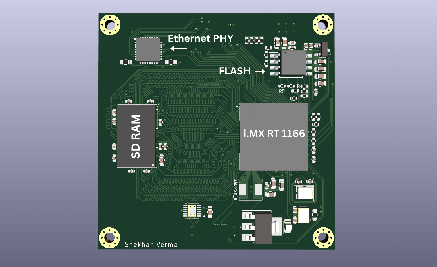
The SoM Features
- i.MX RT 1160 MCU (MIMXRT1166DVM6A)
- 128 Mb SD RAM
- 128 Mb QSPI Flash
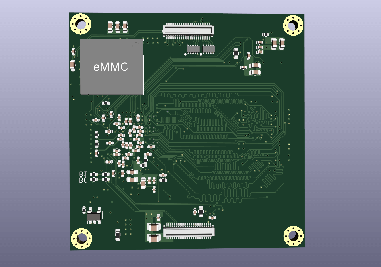
- 4 Gb eMMC
- 10/100 Mbps RMII Ethernet PHY
- 2 Lane MIPI-DSI
- 2 Lane MIPI-CSI
- 2 X USB 2.0
- 2 X I2C
- UART to USB Convertor
- Multiple GPIOs
- 2 X 48 Pin Board-to-Board Connector

Now that we know what we are going to build, let's start with section by section.
I have used Kicad 7 for this project.
1) Power Section and PCB
The SoM is powered by 5V input. A 5V to 3V3 LDO is used to generate votlage rail for MCU, SDRAM , Ethernet PHY and Flash.
A 3V3 to 1V8 LDO is used to generate voltage rail for the eMMC.
The i.MX RT 1160 series MCU comes with a integrated on-chip DC/DC buck convertor to generate two outputs, one output (VDD_DIG) typical 0.7 V~1.15 V, another output (VDD_ANA) typical 1.8 V and its switching frequency is about 1.5 MHz.These voltage rails are required for the working of MCU. Buck convertor requires an external 4.7uH Inductor (with the saturation current > 1.5 A and ESR < 0.1 Ω) for operation. Here I have chosen a shielded inductor for better EMI/EMC performance.
DCDC has two application modes, which is configured by the DCDC_MODE pin
Application mode 0 : DCDC_IN is connected to 3.3V, and DCDC output is 1.8V and 1.0V. DCDC_MODE pin is tied to ground.
Application mode 1 : DCDC_MODE pin is tied to 1.8V. DCDC_IN and DCDC_ANA are both supplied by the external 1.8V power supply, and DCDC outputs DCDC_DIG (1.0V).
You can also use an external PMIC as suggested by NXP but in our case we are going with the built-in route to save money and space on board. (and offcourse to keep things simple :sweat_smile:). In this case I tied the DCDC_MODE pin to ground to use application mode 0.
DCDC_PSWITCH should delay 1 ms with respect to DCDC_IN to guarantee that DCDC_IN is stable before the DC/DC starts up. I have used a RC having time constant of 6.6ms.
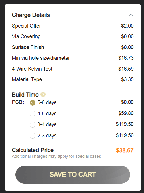
The PCB is a 6 layer impedance controlled board. I decided to make in 50mm x 50mm size because its fabrication cost is lowest on JLC PCB.
To give you a real world idea here is the difference between the PCB fabrication quotes.

When using the on chip DC/DC Convertor we need to place a lot of capacitors directly under the BGA package as recommend by the NXP in their Hardware Design guide (You can find all the links at the end on this post).
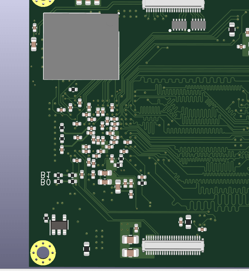
All the capacitors on the back (closely clustered) are decoupling capacitors required for various power rails and signals.
2) SD RAM and NOR FLASH
It is interfaced by SEMC (Smart Extensible memory controller, as NXP likes to call it). It Supports SDRAM, NOR Flash, NAND Flash, SRAM and 8080 Display interface. In this case I have chosen a 128 Mb SDRAM that comes in a TFBGA package.
i.MX RT 1160 uses a external flash to store the code as most modern MCUs and is interfaced by QSPI Protocol.
All the signals are routed on top and bottom layer with controlled impedance and length tuning.
3) Ethernet PHY
PHY means Physical Layer, It is a transceiver component for transmitting and receiving data or Ethernet frames.The physical layer specifies the types of electrical signals, signaling rates, media and connector types, and network topologies.
i.MX RT 11600 do not come with a in-built ethernet PHY and we have to connect an external PHY to the MCU. Here I have used DP83826 from TI as its easily available and very reasonably priced. Initially I was going with a gigabit PHY but most of the PHYs were either out of stock or costing close to the price of the MCU so I settled with a 10/100M PHY.
I have used Reduced MII for interfacing with the PHY as it requires less no. of pins and used the reference of MIMXRT1160-EVK Board. The PHY is placed close to the Board-to-Board connector to reduce the trace lengths of MDI differential pairs. When changing layers Grounding Vias are placed to shorten the signal return path and improve signal integrity.
4) Reset Controller IC.
Although this is optional but NXP recommends to use one for safe operation. The internal DC/DC Convertor resets when Vin drops below 2.6V, so we have chosen a reset controller which resets the MCU before DC/DC convertor resets. The Reset IC also keeps the MCU in reset state till Vin get stable and Vin rises above 2.7V. All of this ensures safe power on and power off sequence.
5) eMMC
I have used a 4Gb eMMC as bulk storage option. It is interfaced using uSDDHC (Ultra Secured Digital Host Controller), yes another fancy long name :dizzy_face: . I have used the eMMC in 4 bit mode because other pins were multiplexed with the NOR flash when using the eMMC in 8 bit mode. As we are using NOR flash as our primary boot option I didn’t want to change the pin mapping. An external 1V8 LDO was used to provide the power to the IC.
These were the major peripherals I exposed in this SoM along with other common things such as oscillators, strapping resistors, etc.
There is still some scope left to route More GPIOs and expose more peripherals. I will update this post when i will do that.
You can find the entire project code here i.MX-RT-1160-SoM.
You can follow me on twitter @shekhu_verma
For Further Reading you can Refer these:-
{{< lb >}}
(You might have to signup to download these)
- i.MX RT1160 Processor Reference Manual
- EMC Design Recommendation on i.MXRT Series
- Hardware Development Guide for the MIMXRT1160/1170 Processor
- MIMXRT1160-EVK Design files
Thank You for reading! :smile: